What are Flow Controls?
JDP supply Flow Control Valves as individual units (in stainless steel or plastic) or complete with chamber (in concrete or HDPE) to bespoke design as part of a SUDS system to control the rate at which stormwater leaves a particular site. A typical application of these valves is to control the flow from storm water attenuation/infiltration tanks preventing downstream flooding during periods of heavy rainfall.
The valve controls fluid flow by hydraulic effect without requiring moving parts. At low flow rates, the valve allows water to enter through the inlet passing to the outlet unrestricted. However, at high flow rates water enters through the inlet with enough energy to create a vortex in the chamber. This vortex controls flow to the specified discharge rate.
Design Requirements
- Head - Depth from invert level of outlet to the top water level upstream
- Flow - Required discharge
- Type of application - ie. foul, combined or stormwater
- Any details of the proposed application, manhole details or control chamber proposals
Applications
Flow Controls can be used wherever there is a need to limit the rate of forward flow of surface water within a drainage system. Typical schemes include:
- Source Control/SUDS Schemes
- Traditional Attenuation Storage
- Energy Dissipation / Velocity Control
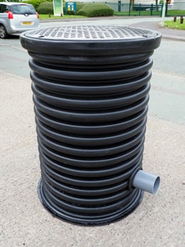
Orichamber - Single Dwelling Orifice Control Chamber
The JFC OriChamber is a prefabricated unit which comprises a Ø600mm Twinwall Chamber with base, 110mm internal and outlet pipework and a pedestrian duty (bolt down) cover. The unit is available in two standard depths of 1.0m and 1.5m incorporating a 150mm sump. (Other depths available to order).
Fitted with a 110mm overflow pipe complete with debris cowl, the pipe and cowl can be removed if the orifice becomes blocked which allows the system to drain down and the blockage removed.
Two number 110mm inlet connection seals are supplied loose with a hole saw enabling them to be fitted easily to the required level and orientation on-site. This offers unique flexibility to the user.
Features & Benefits
- Prefabricated for ease of installation.
- Removable cover and frame to allow shaft to be trimmed on site to suit final levels
- Two inlet seals supplied along with a holesaw to allow them to be located at a suitable level and orientation.
- Overflow pipe which can be removed to allow the system to be drained if the orifice becomes blocked.
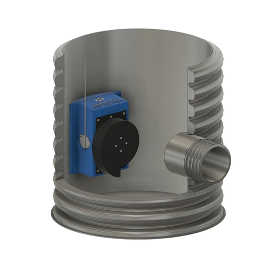
Corriflow - Flow Control Chamber
JFC design a bespoke range of prefabricated catchpit chambers which incorporate either a JFC Hydro-Valve or JFC Hydro-Plate.
These units are individually fabricated to suit specific site information, such as levels, inlet / outlet pipe diameters and orientations, design flow and design head, etc.
Features & Benefits
- Fast Installation.
- Lightweight (compared to conventional construction manholes).
- Designed to fit JFC CorriPipe.
- Prefabricated.
- No requirement for confined space entry (during installation).
- Bespoke as per customer specifications.
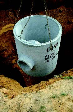
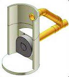
Hydro-Brake
One of the easiest to install, is the Hydro-Brake® Chamber, comprises a precast reinforced concrete chamber base containing a bespoke Hydro-Brake® Flow Control Valve.
A range of outlet pipe sizes are also available to suit site requirements. Once lifted into position, the connecting pipework can be installed. Depending on the overall depth of chamber required, further concrete rings can be added and the cover slab positioned (additional concrete rings and cover slab sold separately).
Features & Benefits
- Bespoke Design - Every Hydro-Brake® Chamber includes a made-to measure Hydro-Brake® Flow Control designed to suit the site specific design. Standard units also have benching for the flow control preformed in the chamber. Step Irons can also be pre-fitted within the chamber if required.
- Inlets/Outlets - Inlet hole(s) of up to 600mm diameter ID can be cored / formed to the customer’s exact specification. A range of outlet sizes is available to suit.
- Rapid Installation - The Hydro-Brake® Chamber is delivered to site as one complete unit with the Hydro-Brake® Flow Control already installed in position. This guarantees the flow control is fitted correctly.
- Simple Construction - The strength of the reinforced concrete chamber eliminates the need for a concrete surround.
- Cost Saving - The use of a Hydro-Brake® Flow Control can reduce the upstream storage volume requirement by up to 30%. This can significantly reduce capital expenditure.
- Minimal Maintenance - The integral Hydro-Brake® Flow Control is totally self-activating, has no moving parts and requires no power to operate.
Hydro-Brake® Chamber Range
| A Diameter (mm) | B Height (mm) | C Height to Invert (mm) | D Height from to Top (mm) | Weight (kg) | Outlet Size Options (mm) | Maximum Inlet Diameter (mm) |
|---|---|---|---|---|---|---|
| 1200 | 1250 | 630 | 620 | 2150 | 150, 225 & 300 | 300 |
| 1500 | 1750 | 710 | 1040 | 3970 | 225/300 & 375/450 | 600 |
Option 1 - Hydro-Brake Chamber with High Level Overflow
This chamber includes an emergency overflow. The design incorporates a cored hole at the desired height to accommodate a reverse backdrop pipe arrangement. This is an alternative design to a weir wall configuration and can be incorporated in the 1200mm, 1500mm and 2000mm diameter chambers (see Option 3).
Option 2 - Hydro-Brake Chamber with Adjacent Penstock
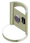
Although the Flow Control includes an integral bypass allowing for drain down and full rodding / jetting, certain Water Companies may also require a completely separate bypass. In these instances we can provide a 150, 225 or 300mm diameter penstock (suitable for up to 6m on seating pressure). The penstock is mounted on the headwall by the side of the Flow Control which can be opened for emergency discharge. Please note that this design is only available in the 1500mm and 2000mm diameter chambers. If required, both the Flow Control and penstock can be mounted on a weir wall (see option 3).
Option 3 - Hydro-Brake Chamber with Integral Weir Wall
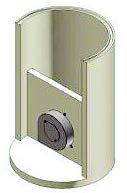
This chamber design includes a reinforced concrete weir wall, complete with premounted Flow Control. The weir wall can be constructed at various heights to suit design requirements. As with the previous option, the weir wall configuration can also include a penstock located alongside the Flow Control (if required). Please note that this option is only available with the 2000mm diameter chamber.
Option 3 - Option 4 - Hydro-Brake Chamber with Complex Flow Controls
With increasing legislation requesting staged discharge rates linked to an assortment of return periods, solving for a single flow rate under a given return period is not always acceptable. Under these circumstances the outflow hydrograph from the control chamber (the point at which the forward flow is restricted) is particularly complicated and cannot usually be achieved with the use of a single flow control device. With the use of appropriate modelling software a solution can be found using ‘complex flow controls’- placing two or more controls in parallel.
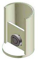
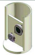
Hydro-Valve
The Hydro-Valve is designed with a curved back to be installed on the internal wall of a 1200mm diameter concrete or plastic chamber.

Features & Benefits
- Manufactured to customised specifications
- Self activating and self cleaning
- Minimal maintenance
- The outlet opening is 3-6 times larger than conventional controls
- Reduce storage requirements by up to 30% compared to an orifice plate
- Curved back with neoprene seal allows ease of installation compared with conventional vortex valves
- The Hydro-Valve unit is attached to the inside of a standard 1200mm (diameter) manhole with six steel anchors (supplied)
- Available to suit rectangular manholes upon request
- Full installation drawings are supplied with Hydro-Valve
JDP can also supply individual Stainless Steel flow control valves