Drainage systems are one of the most important aspects of a working home or property. These carry waste water from toilets, sinks, baths, dishwashers and more, away from the home and into the sewer system.
With construction happening above the drainage system, mistakes made during drainage installation can cause costly problems in future.
This is our guide to the principles of installing a foul water underground drainage system in England & Wales following Building Regulations Part H. We hope it provides some useful information before your next drainage installation project. For Scotland and Northern Ireland seek guidance in the technical documentation available from the Scottish Government and Northern Ireland Assembly.
The principles of underground drainage
Pre-planning
Installing underground drainage requires extensive and careful forward planning. You will need to consider the exact layout of your drainage system and how it will connect together. At the same time, you need to stay in compliance with Building Regulations Part H.
At this early stage, you must ensure that underground drainage is not laid lower than the foundations of any nearby building unless you plan to fill the trench with concrete. The exact requirements can be found in Building Regulations Part H but, to summarise, a trench dug below the foundation:
- within 1 metre of the building must be filled with concrete to the same level as the lowest point of the foundation.
- more than a metre from the building must be filled with concrete up to a level below the foundation that is equal to the distance from the building less 150mm.
Refer to Building Regulations Part H Diagram 8 for more details, or seek further advice from an architect, drainage engineer or relevant specialist.
You should check for existing drains and sewerage systems in the area by contacting the local water authority or referring to the building deeds. To prevent expensive and dangerous problems arising later, existing drains may need to be diverted or otherwise protected. Proximity to public sewers may also force some adjustments to your plan. You may also need to seek written permission from the local sewerage authority before beginning the project.
Where there are obstructions — such as buildings, foundations or water features — the system may need to incorporate more bends after access chambers. Safety is paramount. You will need to make sure, before starting, that the project isn’t going to compromise the foundations of the given property or lot.
Also, it’s essential that your plans ensure an adequate level of hydraulic capacity for current and future demands on the system — especially if you anticipate future work happening. Failing to plan for increased use of the system can lead to blockages, floodage, and even structural failure. A detailed drainage design proposing precise workings of your project can be an invaluable asset to refer to throughout the planning permission and initial installation process.
Planning pipe gradients
By law, foul water drainage systems are required to be self-cleansing. That means that gravity, combined with the force of the water, should drive wastewater into sewer systems without any help.
To ensure this is the case, the recommended minimum gradient (or fall) for foul water drainage is:
- 75mm & 100mm pipeworks when no WC is connected or;
- 1:80 (12.5mm per metre) if a WC is connected to the system, 100/110mm pipework minimum when WC or trade effluent connected, or;
- 1:150 if a minimum of 5 WC are connected (150/160mm pipework only).
The water velocity within the pipe must not fall below 0.70 m/s as this ensures adequate self cleaning and are generally designed to run at a maximum of ¾ full bore. Failure to comply with the above can lead to a higher risk of blockages.
Planning for access
All underground drainage systems need an appropriate number of access points. This is to enable future testing, inspection and maintenance. In your project plan, you will need to plot the locations of inspection chambers, rodding chambers, manholes and other fittings.
Planning for excavation
Before digging trenches for your pipes, you should know that they must not be left open for a long period. Guidance suggests that trenches should be backfilled as soon as possible. Naturally, they must also be fully supported at the sides during the pipe-laying process. Sheet piling is typically used to provide earth retention and excavation support.
These are good reasons to have a solid plan in place before proceeding. To comply with Building Regulations, trenches should be as narrow as possible while allowing 300mm of space for sidefill material.
Other key considerations
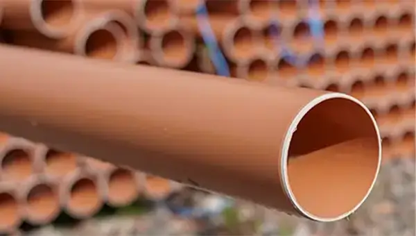
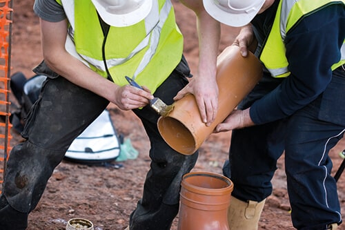
Terracotta pipework
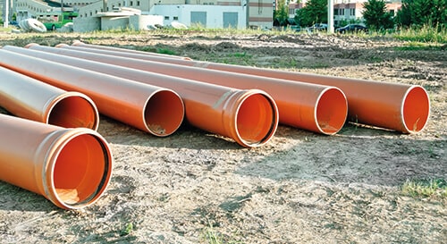
This is critical: you must ensure that all pipes used for underground drainage are the right colour. Terracotta is the official colour scheme for pipes used in foul water systems, but this is sometimes called brown or orange sewer pipe. Failure to follow this one rule could lead to the local Building Authority rejecting your proposal.
Building Control
You will need to contact your local authority Planning & Building Control department so that it can sign off on your project. If you are replacing an existing and damaged drainage system, you are generally not required to get in touch. However, in almost all other cases — including adaptation or a new installation — you are legally required to inform local authorities. You must supply drawings of your plans and organise for an inspection.
Whatever the specifics may be, it’s generally advisable to double-check your work with the relevant local authority — just in case!
Building Regulations
The design of your drainage system should always be guided by UK Building Regulations Part H and Water Industry Specifications
The advice within this guide has been compiled with reference to the Standards listed below. However, we always recommend that you consult these documents before beginning any project work:
- BS 4660 & BS EN 1401: Thermoplastics ancillary fittings of nominal sizes 110 and 160 for below ground gravity drainage and sewerage.
- BS 4962: Specification for plastic pipes and fittings for use as subsoil field drains.
- BS EN 14680: Adhesives for non-pressure thermoplastic pipe systems.
- BS 7158: Plastic inspection chambers for drains and sewers.
- BS EN 124: Gully tops and manhole tops for vehicular and pedestrian areas. Design requirements, type testing, marking, quality control.
- BS EN 295: Vitrified clay pipes & fittings and pipe joints for drains and sewers.
- BS EN 681-1: Elastomeric seals. Material requirements for pipe joint seals used in water and drainage applications.
- BS EN 752: Drain & Sewer Systems outside buildings.
- BS EN 1295-1: Structural design of buried pipelines under various conditions of loading. General requirements.
- BS EN 1610: Construction & Testing of Drains & Sewers.
- BS EN 13476-1 & BS EN 13476-2: Plastics piping systems for non-pressure drainage and sewerage, structured wall piping systems with smooth bore and profiled external surface.
- BS EN ISO 9001: 2008: Quality management systems.
- BS EN ISO 14001: 2004: Environmental management systems requirements with guidance for use.
- WIS 4-08-01: Bedding and sidefill materials for buried pipelines.
Types of pipe used in underground drainage
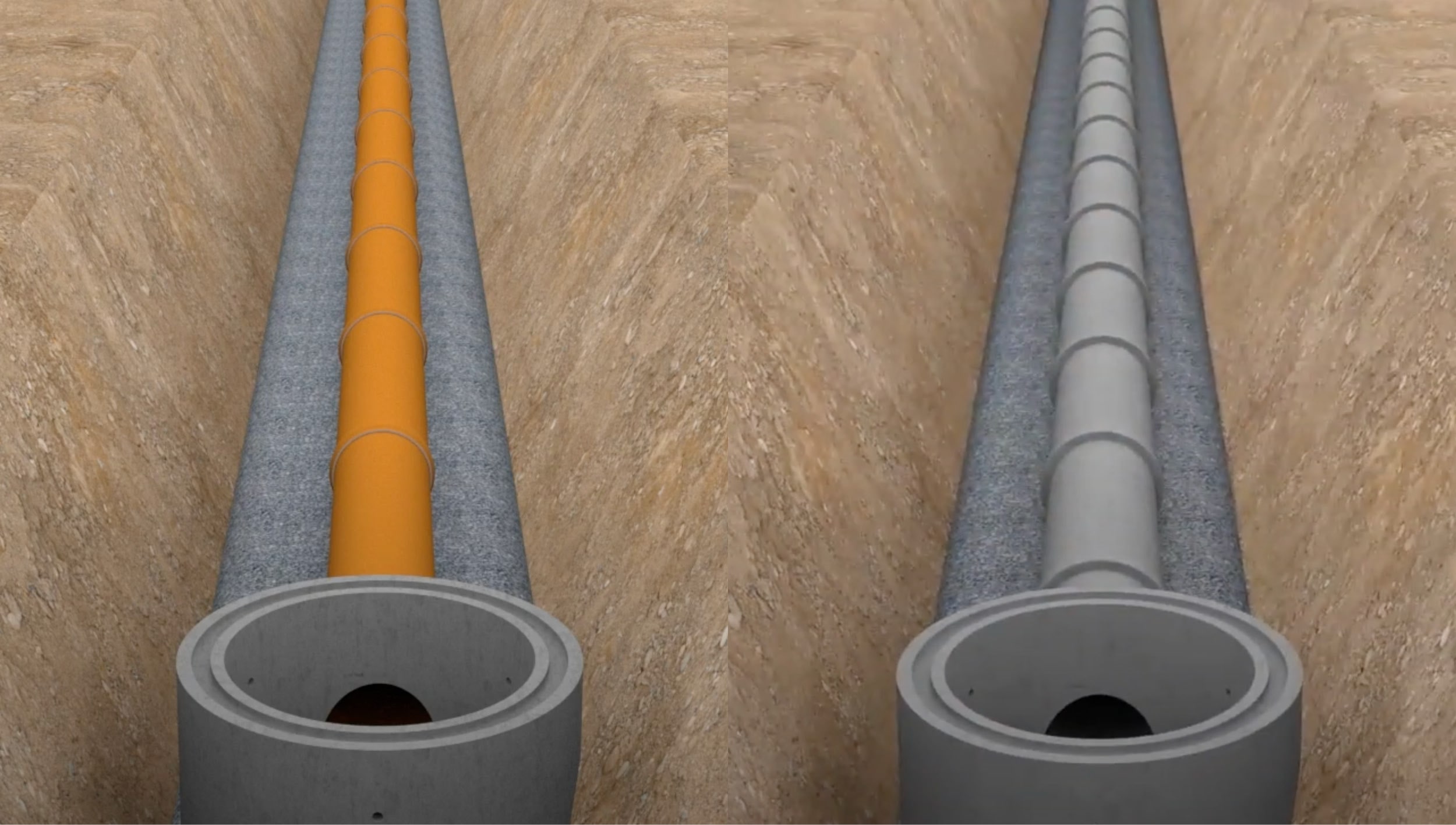
Throughout history and across the world, a variety of pipe types have been used specifically for underground drainage. These include cast iron, glass fibre reinforced plastic (GRP), and even asbestos. The most commonly used types in the UK today tend to be plastic uPVC, concrete and vitrified clay.
Drainage pipes — uPVC, concrete or clay?
Due to its affordability, uPVC has grown in popularity over the years. Plastic pipe is also easier to use, more lightweight, flexible and accommodates longer runs which reduces the number of connectors needed. Plastic is also easy to cut with a standard hacksaw but does need extra care in winter months due to the material's brittleness in the cold increasing the chance of on-site breakages.
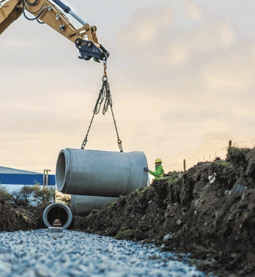
Concrete and clay pipes are still preferred in specific applications and with some local water authorities. This is because they provide greater structural strength in regions where soil movement may be more likely. Concrete and clay pipes also require less backfill material in order to guarantee a sturdy installation. However, these pipes do require more robust tools for cutting such as a power cut-off saw.
Connecting pipes & fittings
During installation of underground drainage there are certain pipes and fittings you will commonly encounter. These will typically be made up of spigot connection or socket format pipes used to connect sections together. Other common aspects of your drainage system will include:
- Plain end drain pipes: chamfered on both ends for ease of installation, generally supplied in lengths of 3m or 6m.
- Drain couplers: for joining two pipes or plain-ended fittings together, using a rubber seal and lubricant to ensure solid installation.
- Standard bends: used for changes in pipe direction, they are generally supplied in either single or double socket varieties and at 15, 30, 45 and 90 degree angles.
- Rest bends: used for connecting ground-floor sanitation to underground drains.
- Gullies: used to filter gases and noxious fumes from the pipes which are connected to underground drainage systems (also drains surface water into the system).
- Inspection chambers: designed to provide access to runs of pipe for maintenance, as well as being used at points where there is a change of direction/diameter/pipe material.
Digging trenches for underground drainage
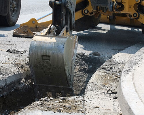
With your plan at hand, you should be ready to dig your trench. Just ensure that you’re ready to begin laying your pipes soon after, as bad weather may lead to the complete collapse of the trench. After digging the trench, you will need to fill it with the appropriate granular material to form a sturdy bed for the pipe runs. Pea shingle is a common example of material used here, although you will find a variety on offer for different applications.
Regarding safety & legality, some helpful best practices to follow include:
- Don’t work in trenches alone without support
- Ensure trenches are fenced off from people, children and pets where needed
- Don’t build your trenches during bad weather
- Keep your trench widths to a standard minimum
- Avoid the edge of the trench — use a ramp of 45 degrees at the trench back if necessary
- Trenches should be 300mm wider than the pipe being laid within
- If deeper than 1200mm, the trench must be checked by the local authority
Laying pipes
The ‘how to’ of laying pipes for your underground drainage system can appear to be quite simple:
- Chamfer the pipe to avoid any leaks or failed air tests at the joint
- Lubricate both connector and pipe
- Push the connector onto the pipe
- Lubricate the receiving connector and open end of pipe (also chamfered)
- Push the next length of pipe into the connector
Yet laying pipes can be one of the trickiest aspects to this type of project. This is largely due to the special care required to ensure gradients/falls will allow the wastewater to flow properly. Here is some common guidance for ensuring compliance when installing your pipes:
- Foul water pipe gradients must ensure wastewater velocity of 0.7m/s at minimum
- For less than 1l/s, a fall of 1:40 (25mm per metre) is appropriate
- For discharge from any WC, a fall of 1:80 (12.5mm per metre) is recommended
- Gullies for foul water drainage must feature a 50mm water seal at minimum
- When passing pipe through a building wall, ensure a lintel is used with 50mm clearance from the pipe on each side of the wall
- Cover pipe holes through building walls with a rigid sheet to block soil and vermin from entering
Bedding for laid pipes
With reference to Building Regulations wherever possible, appropriate backfill and bedding material must be chosen. Grades are listed by soil type and total expected weightload on the drainage system.
Dug material in the trench — such as bricks, stones, etc — should never be used as bedding for pipe runs. Only on rare occasions can the trench itself be used as the pipe’s bedding, e.g. if the soil and surroundings are of a suitable material.
In most instances, pea shingle is the material used for creating the pipe bed. Pea shingle is also often used as a replacement when the soil dug from the trench is inappropriate as sidefill or backfill. However, a huge range of bedding and filler materials are available to suit all kinds of ground conditions, pipes and weight loads. Read Approved Document H of UK Building Regulations for more specific guidance.
To ensure the correct alignment and gradient of pipes within the trench, a guiding line such as a laser or string should be used. After laying the pipe, it should be covered with a layer of material of at least 300mm. Where there is danger of contact — for example, if the pipe is at risk of being unburied and struck during gardening — place a concrete surround around the pipe, or lay red foul sewer marker tape to highlight the presence of the pipe beneath
Access points
Underground drainage pipes tend to suffer from wear and tear over time. Because of these maintenance requirements, all drainage installations must include access points to enable inspection, testing and debris removal.
Access points typically come in the form of manholes, inspection chambers, rodding eyes and gullies that allow maintenance workers to easily rod, clear and repair the system when needed.
You will need to ensure that you leave no more than the maximum distance permitted between access points. As these distances depend on the type of access points used, we recommend referring to Table 13 of Building Regulations Part H for up-to-date guidance.
Backfilling the trench
After installing the drainage run — and air tests have been completed and approval has been granted — the process of backfilling a trench can begin.
Note: the wrong type of backfill material, improperly distributed or compacted, can interfere with a system’s self-cleansing capability. To prevent this from happening — causing unsightly and costly blockages or worse — it’s very important that you use the right ballast. Refer to Diagram 10 in Building Regulations Part H to find details of the suitable backfill materials.
Summary
Broken down to its most elemental, the underground drainage installation process looks something like this:
- Plan where the major components of your system will fit.
- Dig your trenches according to British Standards and Regulations.
- Dig your trenches according to British Standards and Regulations.
- Measure, cut and install pipes, joining components using silicone lubricant.
- Backfill the trench with pea shingle and dug soil, using another backfill material if the soil is not an appropriate cover.
In reality, installing underground drainage can be a sensitive process which requires expert planning and oversight. We hope that, with reference to this guide and to UK Building Regulations, your drainage project can be delivered without a hitch.
And remember, JDP’s high-quality underground drainage product range provides all the parts and fittings needed to complete your installation. As the experts in drainage and water management, JDP’s in-house technical support team can help guide you through legislative requirements and offer advice on the right solution for your project. Don’t hesitate to get in touch to discuss the materials and tools you need.