Constructing a foul water drainage field requires specific rules and regulations you must stick to in order to abide by the law and dispose of foul water in a safe and correct way.
These steps give you guidance on how to install a drainage field to provide secondary treatment to the discharge from a septic tank.
Design the septic tank soakaway to avoid blockages
The design of a foul water drainage system means that blockages should not occur if the system has been installed properly. When installing a septic tank soakaway, it’s important to refer to Building Regulations Part H to ensure the installation meets the required standards, though we have summarised the points below.
Where to lay a drainage field
A drainage field should be:
- 10 metres from any watercourse
- 15 metres from any building
- 50 metres from any water supply
- separate from any other water supply pipes or other underground services
- clear of any access roads, driveways, or paved areas
This ensures both that the pipes cannot be warped or damaged by heavy loads above, such as vehicles or buildings, as well as making sure that the water from the soakaway won’t enter a watercourse, which is in contravention of new guidelines from the Environment Agency.
In general, drainage fields shouldn't be located under/near:
- Buildings
- Boundaries
- Driveways
- Parking areas
- Trees
- Rivers, streams or other watercourses
- Other drainage fields or soakaways (including surface water soakaways)
Establishing the groundwater table
Because the water from a soakaway filters directly into the ground, it’s important to establish that the ground can handle the additional water before installation begins. The first step is to determine the position of the standing groundwater table.
You can do this by digging a 1m2 trial hole to a depth of at least 1.5m below the invert level of the proposed drainage field pipework. The groundwater table should not rise to within 1m of the invert level. Don’t forget that the groundwater levels will be different at different times of the year, so be sure to take that into account.
Percolation Test
A percolation test ensures that the ground has sufficient drainage to handle the amount of water that will come from the drainage field. A percolation test can be conducted by taking the following steps:
- Dig a 300mm square hole to a depth of 300mm below the proposed invert level of the drainage field..
- Fill the hole with water and allow it to seep away overnight.
- Refill the hole with water the next day and time how long it takes for the water to seep away from 75% full to 25% full.
- Divide this time by 150. Drainage fields are only suitable if the resulting number is between 12 and 100.
- Repeat this test at least three times with at least two different holes. The test shouldn’t be carried out during heavy rain, severe frost, or drought.
For more detailed advice about percolation tests, check out our “How to perform a percolation test” article.
Geotextile membranes
Geotextiles are permeable fabrics that improve ground stability and aid water filtration while preventing layers of soil from mixing with each other.
A geotextile plays an important role in protecting the drainage field once it is installed. If the pipes were laid and covered without one, the drainage field would be at risk of being blocked by silt, leaves, or compressed soil from above. A geotextile keeps them at bay so that the drainage holes aren’t blocked and the flow of water is unimpeded.
Design and Construction
As per Building Regulations 2010 Drainage and Waste Disposal Part H:
- Drainage fields should be designed and constructed to ensure aerobic contact between the liquid effluent and the subsoil.
- Drainage fields should be constructed using perforated pipe, laid in trenches of a uniform gradient which should not be steeper than 1:200.
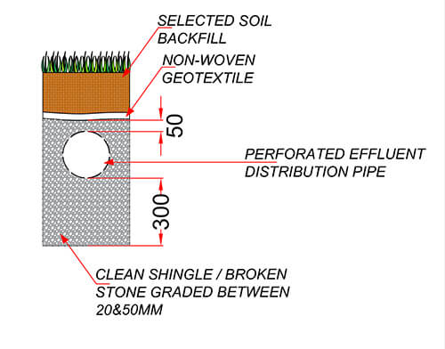
- Pipes should be laid on a 300mm layer of clean shingle or broken stone graded between 20mm and 50mm.
- Trenches should be filled to a level 50mm above the pipe and covered with a layer of non-woven geotextile to prevent the entry of silt. The remainder of the trench can be filled with soil; the distribution pipes should be laid at a minimum depth of 500mm below the surface. Drainage trenches should be from 300mm to 900mm wide, with areas of undisturbed ground 2m wide being maintained between parallel trenches.
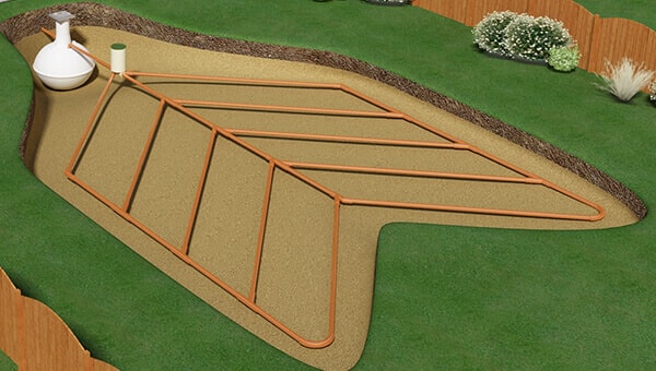
- An inspection or a sample chamber should be installed between the septic tank and the drainage field.
- Drainage fields should be set out as a continuous loop fed from the inspection chamber.
Contact JDP's Technical Support Team who will be able to assist you with further queries regarding septic drainage field construction.