Surface Water Drain Discharge
Surface water drains normally discharge to a watercourse or indirectly into underground waters (groundwater) via a soakaway. Contamination of surface water by oil, chemicals or suspended solids can cause these discharges to have a serious impact on the receiving water.
Oil separators are installed on surface water drainage systems to protect receiving waters from pollution by oil, which may be present due to minor leaks from vehicles and plant, from accidental spillage or due to deliberate and illegal tipping into drains.
Note that throughout this section the term ‘separator’ is used instead of the term ’interceptor’. The terms have the same meaning. It is a mandatory requirement under PPG3 (Pollution Prevention Guidelines), to fit an automatic oil level warning device (alarm). Additionally a silt capacity within the tank (preferred) or in an upstream catchpit is required under PPG3.
Bypass Separator
Applications
Bypass separators are used when it is considered an acceptable risk not to provide full treatment, for very high flows, and are used, where the risk of a large spillage and heavy rainfall occurring at the same time is small .e.g
- Surface car parks
- Roadways
- Lightly contaminated commercial areas
Features & Benefits
- Light and easy to install
- Class 1 and Class 2 designs
- Independently tested and performance sampled, certified by the BSI
- Comprehensive range with rapid availability
- Inclusive of silt storage volume
- Oil alarm system available (mains, solar & GSM options)
- Fitted inlet/outlet connectors
- Vent points within necks
- Extension access shafts for deep inverts
- Maintenance from ground level
Information required to specify a nominal size Bypass Separator:
- The calculated flow rate (NS) or the drainage area served (m3). Designs are based on the assumption that any interconnecting pipework fitted elsewhere on site does not impede flow into or out of the separator.
- The required discharge standard. This will decide whether a Class 1 or Class 2 unit is required
- The drain invert inlet depth
- Pipework type, size and orientation
Each bypass separator design includes the necessary volume requirements for:
- Oil separation capacity
- Oil storage volume
- Silt storage capacity
- Coalescer
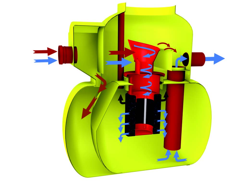
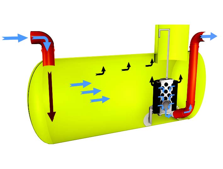
Operation
100% of the liquid, up to the unit’s designated flow passes through both chambers of the unit. The separation chamber retains the lighter than water pollutants, oils and petrol which rise to the surface. These pollutants are stored within the separator. The separated water discharges from the unit by gravity. If the flow rate rises above the unit’s nominal size rating, the excess flow is diverted by a bypass arrangement and discharged without passing through the separation chamber. This ensures that excess flows will not cause ‘wash out’ of stored pollutants.
Performance
The unit is designed to treat 10% of peak flow. The calculated drainage areas served by each separator are indicated according to the formula given by PPG-3 NSB = 0.0018A(m2). Flows generated by higher rainfall rates will pass through part of the separator and bypass the main separation chamber.
Class 1 separators are designed to achieve a concentration of 5mg/litre of oil under standard test conditions.
Class 2 separators are designed to achieve a concentration of 100mg/litre of oil under standard test conditions.
Full Retention Separator
Applications
- Fuel distribution depots
- Vehicle workshops
- Scrap yards
- Garage forecourts
Features & Benefits
- Light and easy to install
- Comprehensive range
- Independently tested and performance sampled, certified by the BSI
- Class 1 and Class 2 designs
- Inclusive of silt storage volume
- Oil alarm system available (mains, solar & GSM options)
- Rapid availability
- Fitted inlet/outlet connectors
- Vent points within necks
- Extension access shafts for deep inverts
- Maintenance from ground level
Each full retention separator design includes the necessary volume requirements for:
- Oil separation capacity
- Oil storage volume
- Silt storage capacity and incorporating a Coalescer (class 1 units only)
- Coalescer
- Automatic closure device (ACD)
Operation
Contaminated water enters the unit, the internal design and configuration ensures that the liquid is retained for a sufficient period to ensure inactive conditions within the separator. Lighter than water pollutants, such as oils and petrol, rise to the surface of the water and are retained within the separator. Separated liquid discharges. An automatic closure device seals off the outlet when the retained oil reaches the pre-determined level. Retained oil must be emptied from the unit once that level of oil is reached and the closure device is operated.
Performance
Under PPG3 guidelines Separators are tested to BS EN 858-1. The NS number denotes the flow at which the separator operates and is only able to be applied to products which have been independently tested and certified. The British Standards Institute (BSI) has tested the required range of separators and has certified their performance in relation to their flow and process performance. Forecourt separators specifically to retain on site the maximum spillage likely to occur on a petrol filling station or other refuelling site are also available.
Washdown & Silt Separator Range
This unit can be used in areas such as car wash and other cleaning facilities that discharge directly into a foul drain, which feeds to a municipal treatment facility. If emulsifiers are present the discharge must not be allowed to enter a NS class 1 or class 2 unit.
Features & Benefits
- Light and easy to install
- Comprehensive range
- Inclusive of silt storage volume
- Rapid availability
- Fitted inlet/outlet connectors
- Vent points within necks
- Extension access shafts for deep inverts
- Maintenance from ground level
Performance
Washdown facilities must not be allowed to discharge directly into either surface water or any oil/water separator discharging into a surface water as they utilise emulsifiers, soaps and detergents, which can dissolve and disperse the oils and upset the separation process.
Installation
Siting the Unit
- The tank should be as far away from habitable buildings as is economically practicable. The direction of the prevailing wind should be considered in relation to any properties when siting the works. The sludge emptying contractor’s vehicle will probably have a maximum reach of 30 metres, but the depth from the ground level to the bottom of the tank must not exceed 5 metres.
- The installation should be carried out in accordance with the requirements of the Construction and Building Regulations. An inspection chamber should be installed upstream of the Separator.
- It is a mandatory requirement under PPG3 (Pollution Prevention Guidelines), to fit an automatic oil level warning device (alarm). Additionally a silt capacity within the tank (preferred) or in an upstream catchpit is required under PPG3.
BEFORE INSTALLING YOUR TANK
- Read Full Installation Guide provided with delivery of goods.
- Ensure access for desludging tanker. (Building regulations suggest 30m max).
- Check orientation and heights of inlet and outlets.
- Use a pump to keep excavation clean and free from rising ground water during installation.
DO:
- Use the correct backfill material.
- Site tank at furthest practical location from habitable dwellings. Most regulations recommend a minimum of 3m.
- Fit the correct duty cover & frame LOCKABLE.
- Lift the tank using adequate ropes or slings through both of the lugs fitted either side of the neck.
- Fill the tank with water once bedded in hole before pouring concrete to prevent movement.
DO NOT:
- Subject the tank to impact or contact with sharp edges.
- Add neck extensions to the tank, nor, build a brick manhole above the tank neck (as this increases burial depth of the tank beyond that which it was designed for). We do not recommend extending the neck of the tank under any circumstances.
- Install tank deeper than the depth that the fitted neck will allow.
- Install in trafficked areas without a suitable load bearing slab.
- Site the tank so that it is subjected to excess ground pressure (e.g. sloping sites) or applied loads such as may be generated by the proximity of vehicular traffic.
- Lift using only one of the lugs.
- Fill an unsupported tank.
Service Agreement
Although of a minimal nature, the separator must be serviced periodically to help ensure many years of trouble-free operation. This is a requirement of the PPG3 guidelines.
The period between maintenance operations may vary depending on the location and use of the interceptor, therefore routine inspections should be undertaken at least every 6 months, and a log kept of the inspection date, depth of oil, depth of silt and any cleaning undertaken.