What are Sewage Treatment Plants?
JDP offers a comprehensive range of sewage treatment plants designed to treat the sewage from developments where access to the main sewer is not possible. From those suitable for the smallest units, through to plants for large commercial, public & industrial buildings.
The correct sizing of the plant is crucial to the quality of the water discharged as is the prevention of grease build up inside that plant. See Grease Traps later in this section.
Sewage treatment plants operate by providing an environment in which aerobic bacteria are cultured. These bacteria survive by using biological matter in the sewage as a food source. To provide optimum treatment the bacteria need free access to oxygen and immersion in the sewage effluent. The majority of package plant work by providing a fixed medium that the bacteria adhere to, and a means of interfacing this with regular supplies of oxygen and biological material.
How do Treatment Plants work?
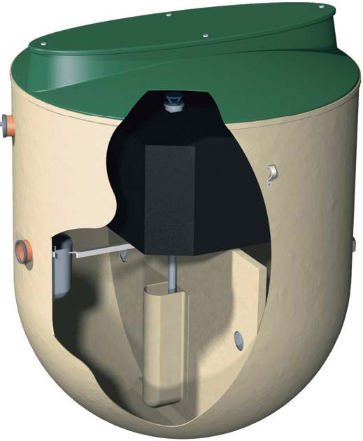
Primary Settlement Tank
The gross solids form sludge at the bottom of the tank and lighter social debris forms a crust on the surface. The sludge and crust should be removed periodically in accordance with the plant design. The settled liquor that is contained between the sludge and crust passes forward for treatment in the Biological Aerated Filter.
Treatment
This is the treatment zone and it contains a set of inactive modular media blocks that provide a large surface area on which naturally occurring bacteria can develop. The bacteria require oxygen which is supplied by a linear low-pressure compressor via porous membranes, beneath the media bed. The bacteria naturally feed on the settled sewage to further reduce the levels of Biological Oxygen Demand (BOD), Suspended Solids (SS) and Ammonia (NH3) in order to comply with the evermore stringent requirements of the Regulatory Authorities.
Final Settlement Tank
As the bacteria in the Biological Aerated Filter dies off, it falls away from the media and is passed forward to the final settlement tank where it settles out, further reducing the level of suspended solids in the final effluent. Design features include a benched bottom to ensure concentrated settlement, and a sludge return system returning settled humus sludge back to the first stage of the primary settlement tank.
Final Effluent Discharge
Depending on the local ground conditions and the final effluent quality required by the local Environment Agency (England and Wales) Scottish Environmental Protection Agency (Scotland), discharge can be directly into a water course. However in some cases an additional filter bed constructed of smooth internal half perforated pipe, usually EN1401-1 standard is required as part of the system to further break down the effluent.
Reed beds are also available from JDP where local water authorities request a better quality of effluent than that discharged from a standard treatment plant.
Features & Benefits
- Low running costs
- Very low maintenance
- Lockable cover
- High process performance
- Near silent operation
- Very low energy consumption
- No nauseous smells or pollution to offend neighbours
- Actively treats sewage before safely discharging it
- Complies with environmental regulations
- Improves resale value of the property
- Available with standard gravity outlet, or optional pumped outlet where the soakaway or discharge point is at a higher level. The outlet pump is housed within the body of the plant.
Applications
The range of treatment plants provides an economic solution for anything from a single dwelling upwards. These plants are designed to suit the specific application using the following criteria:
- Maximum potential population being served.
- Final effluent quality required by the local Environment Agency (England and Wales) or Scottish Environmental Protection Agency (Scotland).
It is important to ensure you obtain the relevant authorising consent from the EA (England and Wales) or SEPA (Scotland) before installing. Your local JDP branch can give advice on how to obtain this.
Treatment plants are designed and built to suit the individual requirements of each application. However there are recognised standard sizes and treatment qualities.
Building regulations apply. PPG4 Guidelines apply from July 2008. EN12566 Part 3 - The New European Standard for Domestic Sewage Treatment Plants.
E-Range Sewage Treatment System Features
- Certified to EN 12566 standard and compliant with Building Regulations
- Subject to consent and site conditions, the system can discharge directly to a watercourse
- No mechanical or electrical components within the system - low running and maintenance costs
- Low level visibility in the garden with a lockable child-proof cover
- Controlled ventilation - minimises risk of odour nuisance
- Easy to install and maintain with annual desludging/emptying
| Daily Flow (m3/day) | BOD Load (kg/day) | Weight Empty (kg) | Outside Diameter (m) | Depth (m) | Inlet Invert (m) | Inlet Invert to Base (m) | Outlet Invert (m) | Motor Rating (watts) | |
|---|---|---|---|---|---|---|---|---|---|
| E006 | 1.2 | 0.36 | 195 | 1.9 | 2.2 | 1.0* | 1.2 | 1.100 | 60 |
| E006 IPS | 1.2 | 0.36 | 220 | 1.9 | 2.2 | 1.0* | 1.2 | 0.605 | 60 |
| E012 | 2.4 | 0.72 | 217 | 1.9 | 2.7 | 1.0* | 1.7 | 1.100 | 60 |
| E012 IPS | 2.4 | 0.72 | 260 | 1.9 | 2.7 | 1.0* | 1.7 | 0.605 | 60 |
| E018 | 3.6 | 1.10 | 445 | 2.7 | 2.6 | 1.0* | 1.6 | 1.100 | 150 |
| E018 IPS | 3.6 | 1.10 | 471 | 2.7 | 2.6 | 1.0* | 1.6 | 0.605 | 150 |
| E025 | 5.0 | 1.50 | 470 | 2.7 | 2.6 | 1.0* | 1.6 | 1.100 | 150 |
| E025 IPS | 5.0 | 1.50 | 495 | 2.7 | 2.6 | 1.0* | 1.6 | 0.655 | 150 |
* There are two depths od inlet in the range 1.0m and 1.5m. For further assistance and advice on selecting the appropriate E-Range system please contact our Technical Sales who will be pleased to help. We can arrange for one of our local Area Managers to visit your site to advise on model selection and legislation. We can also recommend specialist installers if requested. This advice service is supplied free of charge.
Delta Sewage Treatment System
The best designs are the simplist. So if you require trouble free sewage treatment, you're sure to be impressed with the Delta. Fuidised, fixed-film biozones are used as the operating process, resulting in a cleaner, quieter and more efficient treatment plant.
- Unobtrusive below ground installation
- Suitability for varying invert levels
- Excellent durability
- Low profile results in shallow depth excavation
- Simple maintenance with easy desludging
- Sludge recycle pump in the final settlement tank
- Compliant with BS En-12566 Part 3
- Proven standards of discharge - 20mg/l BOD, 30mg/l S.S. and 10mg/l ammonia in domestic applications
| Number of Turrets | Inlet Invert (mm) | Oultet (mm) | Overall Length (mm) | Height (inc. feet) (mm) | Overall Diameter (mm) | Invert & Outlet Diameter (mm) | |
|---|---|---|---|---|---|---|---|
| Delta 1 | 1 | 450 | 550 | 2720 | 1727 | 1530 | 110 |
| 1 | 750 | 850 | 2720 | 2027 | 1530 | 110 | |
| 1 | 1000 | 1100 | 2720 | 2277 | 1530 | 110 | |
| Delta 2 | 3 | 750 | 850 | 3244 | 2470 | 1916 | 110 |
| 3 | 1000 | 1100 | 3244 | 2720 | 1916 | 110 | |
| Delta 3 | 3 | 750 | 850 | 3976 | 2470 | 1916 | 110 |
| 3 | 1000 | 1100 | 3976 | 2720 | 1916 | 110 | |
| Delta 4 | 3 | 750 | 850 | 5550 | 2470 | 1916 | 160 |
| 3 | 1000 | 1100 | 5550 | 2720 | 1916 | 160 |
Installation
Siting the Unit
- British Standard BS: 6297-1983 recommends that sewage treatment works should be as far away from habitable buildings as is economically practicable. The direction of the prevailing wind should be considered in relation to any properties when siting the works. The sludge emptying contractor’s vehicle will probably have a maximum reach of 30 metres, but the depth from the ground level to the bottom of the tank must not exceed 5 metres.
- The installation should be carried out in accordance with the requirements of the Construction and Building Regulations. An inspection chamber should be installed upstream of the Treatment Plant. For discharge quality sampling purposes a sampling chamber can be provided (optional extra).
BEFORE INSTALLING YOUR TANK
- Read Full Installation Guide provided with delivery of goods.
- Ensure Building Regulation approval.
- Ensure consent of discharge is approved from the environment agency.
- Ensure access for desludging tanker. (Building regulations suggest 30m max).
- Check orientation and heights of inlet and outlets.
- Use a pump to keep excavation clean and free from rising ground water during installation.
DO
- Use the correct backfill material.
- Site tank at furthest practical location from habitable dwellings. Most building regulations recommend a minimum of 7m.
- Fit the correct cover & frame (pedestrian duty) LOCKABLE.
- Consider drainage falls, generally 1 in 60/70 between house and tank and max. 1 in 200 for filter bed system.
- Lift the tank using adequate ropes or slings through both of the lugs fitted either side of the neck.
DO NOT
- Subject the tank to impact or contact with sharp edges.
- Add neck extensions to the tank, nor, build a brick manhole above the tank neck (as this increases burial depth of the tank beyond that which it was designed for). We do not recommend extending the neck of the tank under any circumstances.
- Install tank deeper than the depth that the fitted neck will allow.
- Install in trafficked areas without a suitable load bearing slab.
- Site the tank so that it is subjected to excess ground pressure (e.g. sloping sites) or applied loads such as may be generated by the proximity of vehicular traffic.
- Lift using only one of the lugs.
- Fill an unsupported tank.
Service Agreement
Although of a minimal nature, it is advised that the plant is serviced periodically to help ensure many years of trouble-free operation. Service Agreements are available through your local JDP.
This is a requirement of the new PPG4 guidelines.